
01
Overhead line condition
Connector, damper and surface-temperature screening along transmission corridors.
Radiometric thermal imagery turns temperature into a measurable input for asset condition, moisture mapping and vegetation management along energy corridors.
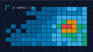
Flown at a controlled altitude, calibrated radiometric sensors record surface temperature across the whole corridor in a single pass. Temperature anomalies are then related to asset condition, moisture regimes and vegetation impede state, giving operations teams a categorised picture of where to look, not a thermal postcard.
Moisture and evapotranspiration indices derived from the thermal band complement the multispectral suite, supporting drainage assessment, embankment screening and habitat moisture mapping in the same mission.
Readings are cross-referenced to asset registers and delivered as GIS layers with anomaly classification, so maintenance programmes can prioritise interventions on evidence.
 Division 03
Method
Target assets, radiometric calibration and anomaly thresholds agreed in advance.
Thermal lines flown at constant altitude with calibration targets where practical.
Emissivity correction applied; anomalies classified against asset registers.
Temperature layers and anomaly plans issued to your GIS.
Deliverables
Temperature as engineering data, calibrated and categorised for your asset management process.
Typically Applied To
01
Connector, damper and surface-temperature screening along transmission corridors.
02
Whole-site thermal baseline feeding inspection and outage planning.
03
Vegetation impede and surface condition over buried corridors.
Continue Reading